Technical Summary & Field Standards
Calculate concrete footing depth and width based on frost line codes, soil bearing capacity, and post loads. Step-by-step dimensions for decks and sheds.
Building codes mandate that exterior concrete footings must extend at least 12 inches below the local frost line depth and measure at least twice the width of the supported post or wall (typically 16 to 24 inches square). Sizing your footings below the frost penetration line prevents freeze-thaw heaving, while the surface area distributes building loads across undisturbed native soil without settling.
Frost Line Depth and Footing Thickness Requirements
The International Residential Code (IRC Section R403) requires footings to bear on undisturbed soil below the regional frost heave zone:
- Northern US Zones: Frost lines range from 36 to 60 inches deep.
- Southern US Zones: Frost lines range from 12 to 24 inches deep.
- Footing Thickness: The concrete footing thickness must equal or exceed the width of the footing projection (minimum 6 inches thick for residential decks and light outbuildings; 8 to 12 inches for residential additions).
Concrete Footing Sizing Table by Soil Capacity
| Supported Load (lbs) | Clay Soil (1,500 psf) | Sandy Silt (2,000 psf) | Dense Gravel (3,000 psf) | Footing Thickness | 80 lb Bags Needed (18" Pad) |
|---|---|---|---|---|---|
| 1,500 lbs (Corner Deck Post) | 14 in square | 12 in square | 10 in round | 6 inches | 2 bags |
| 3,000 lbs (Center Deck Post) | 18 in square | 16 in square | 14 in square | 8 inches | 3 bags |
| 4,500 lbs (Heavy Beam Load) | 22 in square | 18 in square | 16 in square | 8 inches | 4 bags |
| 6,000 lbs (Two-Story Deck) | 26 in square | 22 in square | 18 in square | 10 inches | 6 bags |
Step-by-Step Footing Math and Pouring Rules
To size and pour a footing correctly:
- Calculate Post Tributary Area: A deck post supporting half the joist span (6 ft) and half the beam span (8 ft) carries 48 sq ft of deck. At a standard 50 psf total design load (40 live + 10 dead), the post load equals 2,400 lbs.
- Determine Footing Area: In average 2,000 psf soil, required area = 2,400 lbs ÷ 2,000 psf = 1.20 sq ft. An 18-inch round footing provides 1.77 sq ft, exceeding code minimums.
- Excavation & Base Prep: Dig down 6 inches deeper than the frost line, add 6 inches of compacted crushed stone for base drainage, and pour the concrete pad. Place two #4 rebar crosses in the lower third for tensile reinforcement.
Form Tubes (Sonotubes) vs. Trench-Poured Piers
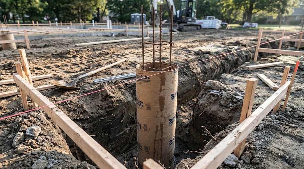
When building cylindrical post piers above the spread footing, builders use round cardboard form tubes (commonly known by the brand name Sonotube):
- Trench Pouring (Below Grade): The spread footing pad at the base can be poured directly into clean, square-dug earth at the bottom of the trench, provided the soil sidewalls are firm and have not collapsed.
- Form Tubes (Above Grade): Place the cardboard tube centered on top of the poured footing pad, extending at least 6 inches above final finished grade. Extending the concrete pier above grade protects the wood post from soil moisture, splashback rot, and termite tunnels.
- Backfill Consolidation: Backfill soil around the form tube in 6-inch lifts, tamping lightly each time to keep the tube plumb before pouring concrete into the tube.
Critical Hardware: Post Anchors and Wet-Set Bolts
Never bury wooden posts directly into concrete footings, even pressure-treated lumber. Chemical preservatives eventually leach into surrounding concrete, causing subterranean rot that cannot be inspected:
- Elevated Standoff Bases: Install galvanized post bases (such as Simpson Strong-Tie ABU or ABA series) that provide a 1-inch standoff plate between the concrete surface and the bottom wood grain. This gap prevents capillary water absorption.
- Embedded Anchor Bolts: Wet-set 1/2-inch hot-dipped galvanized J-bolts or threaded anchor rods directly into the center of the wet concrete pier. Leave 1.5 to 2 inches of threaded rod exposed to receive the standoff base and washer nut.
- Curing Time Before Loading: Allow pier concrete to hydrate and cure for at least 72 hours before erecting posts, and a full 7 days before loading with beams and heavy deck joists.
To calculate concrete volume and bag counts for any cylindrical sonotube or square pad, use our concrete calculator.